Digital to Analog Converter. More...
Functions | |
| void | dac_enable (uint32_t dac, int channel) |
| DAC Channel Enable. More... | |
| void | dac_disable (uint32_t dac, int channel) |
| DAC Channel Disable. More... | |
| void | dac_dma_enable (uint32_t dac, int channel) |
| DAC Channel DMA Enable. More... | |
| void | dac_dma_disable (uint32_t dac, int channel) |
| DAC Channel DMA Disable. More... | |
| void | dac_trigger_enable (uint32_t dac, int channel) |
| DAC Channel Trigger Enable. More... | |
| void | dac_trigger_disable (uint32_t dac, int channel) |
| DAC Channel Trigger Disable. More... | |
| void | dac_set_trigger_source (uint32_t dac, uint32_t source) |
| Set DAC Channel Trigger Source. More... | |
| void | dac_set_waveform_generation (uint32_t dac, int channel, enum dac_wave wave) |
| Set DAC Channel Waveform Generation mode for one or both channels. More... | |
| void | dac_disable_waveform_generation (uint32_t dac, int channel) |
| Disable DAC Channel Waveform Generation. More... | |
| void | dac_set_waveform_characteristics (uint32_t dac, int channel, int mamp) |
| Set DAC Channel LFSR Mask or Triangle Wave Amplitude. More... | |
| void | dac_load_data_buffer_single (uint32_t dac, uint16_t data, enum dac_align align, int channel) |
| Load DAC Data Register. More... | |
| void | dac_load_data_buffer_dual (uint32_t dac, uint16_t data1, uint16_t data2, enum dac_align align) |
| Load DAC Dual Data Register. More... | |
| void | dac_software_trigger (uint32_t dac, int channel) |
| Trigger the DAC by a Software Trigger. More... | |
| void | dac_buffer_enable (uint32_t dac, int channel) |
| DAC Channel Output Buffer Enable. More... | |
| void | dac_buffer_disable (uint32_t dac, int channel) |
| DAC Channel Output Buffer Disable. More... | |
Detailed Description
Digital to Analog Converter.
This library supports the Digital to Analog Conversion System in the STM32 series of ARM Cortex Microcontrollers by ST Microelectronics.
The DAC peripheral found on many of the devices in the STM32 lineup, sometimes with only one channel, but normally with two channels.
Two DAC channels are available, however unlike the ADC channels these are separate DAC devices controlled by the same register block.
The DAC is on APB1. Its clock must be enabled in RCC and depending on specific family, the GPIO ports set to alternate function output before it can be used. On most families, the GPIO pins should be configured to Analog IN to avoid parasitic consumption. The digital output driver is disabled so the output driver mode (push-pull/open drain) is arbitrary.
The DAC has a holding (buffer) register and an output register from which the analog output is derived. The holding register must be loaded first. If triggering is enabled the output register is loaded from the holding register after a trigger occurs. If triggering is not enabled the holding register contents are transferred directly to the output register.
- Note
- To avoid nonlinearities, do not allow outputs to range close to zero or V_analog.
Dual Channel Conversion
There are dual modes in which both DACs are used to output data simultaneously or independently on both channels. The data must be presented according to the formats described in the datasheets. A convenience function dac_load_data_buffer_dual is provided for software controlled use.
A variety of modes are available depending on whether independent or simultaneous output is desired, and whether waveforms are to be superimposed. Refer to the datasheets.
If DMA is used, only enable it for one of the channels. The DMA requests will then serve data in dual format to the data register dedicated to dual mode. The data will then be split and loaded to the appropriate DAC following the next trigger. There are three registers available, one for each of the formats: 12 bit right-aligned, 12 bit left-aligned and 8 bit right-aligned. The desired format is determined by specifying the appropriate register to the DMA controller.
Basic DAC handling API.
Set the DAC's GPIO port to Analog IN. Enable the DAC clock. Enable the DAC, set a trigger source and load the buffer with the first value. After the DAC is triggered, load the buffer with the next value. This example uses software triggering and added noise. The trigger and further buffer load calls are made when data is to be sent out.
Simultaneous Dual DAC with DMA.
This example in part sets up the DAC channel 1 DMA (DMA2 channel 3) to read 16 bit data from memory into the right-aligned 8 bit dual register DAC_DHR8RD. Both DAC channels are enabled, and both triggers are set to the same timer 2 input as required for simultaneous operation. DMA is enabled for DAC channel 1 only to ensure that only one DMA request is generated.
LGPL License Terms libopencm3 License
LGPL License Terms libopencm3 License
Function Documentation
◆ dac_buffer_disable()
| void dac_buffer_disable | ( | uint32_t | dac, |
| int | channel | ||
| ) |
DAC Channel Output Buffer Disable.
Disable a digital to analog converter channel output drive buffer. Disabling this will reduce power consumption slightly and will increase the output impedance of the DAC. The buffers are enabled by default after a reset.
- Parameters
-
[in] dac the base address of the DAC. DAC register base addresses [in] channel with DAC mask. DAC Channel Identifier
Definition at line 66 of file dac_common_v1.c.
References DAC_CHANNEL1, DAC_CHANNEL2, DAC_CHANNEL_BOTH, DAC_CR, DAC_CR_BOFF1, and DAC_CR_BOFF2.
◆ dac_buffer_enable()
| void dac_buffer_enable | ( | uint32_t | dac, |
| int | channel | ||
| ) |
DAC Channel Output Buffer Enable.
Enable a digital to analog converter channel output drive buffer. This is an optional amplifying buffer that provides additional drive for the output signal. The buffer is enabled by default after a reset and needs to be explicitly disabled if required.
- Parameters
-
[in] dac the base address of the DAC. DAC register base addresses [in] channel with DAC mask. DAC Channel Identifier
Definition at line 42 of file dac_common_v1.c.
References DAC_CHANNEL1, DAC_CHANNEL2, DAC_CHANNEL_BOTH, DAC_CR, DAC_CR_BOFF1, and DAC_CR_BOFF2.
◆ dac_disable()
| void dac_disable | ( | uint32_t | dac, |
| int | channel | ||
| ) |
DAC Channel Disable.
Disable a digital to analog converter channel.
- Parameters
-
[in] dac the base address of the DAC DAC register base addresses [in] channel with DAC mask DAC Channel Identifier
Definition at line 159 of file dac_common_all.c.
References DAC_CHANNEL1, DAC_CHANNEL2, DAC_CHANNEL_BOTH, DAC_CR, DAC_CR_EN1, and DAC_CR_EN2.
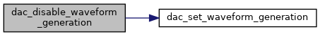
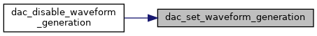
◆ dac_disable_waveform_generation()
| void dac_disable_waveform_generation | ( | uint32_t | dac, |
| int | channel | ||
| ) |
Disable DAC Channel Waveform Generation.
- Note
- this is equivalent to dac_set_waveform_generation (dac, channel, DAC_WAVE_DISABLE)
- Parameters
-
[in] dac the base address of the DAC. DAC register base addresses [in] channel with DAC mask. DAC Channel Identifier
Definition at line 332 of file dac_common_all.c.
References dac_set_waveform_generation(), and DAC_WAVE_DISABLE.
◆ dac_dma_disable()
| void dac_dma_disable | ( | uint32_t | dac, |
| int | channel | ||
| ) |
DAC Channel DMA Disable.
Disable a digital to analog converter channel DMA mode.
- Parameters
-
[in] dac the base address of the DAC. DAC register base addresses [in] channel with DAC mask. DAC Channel Identifier
Definition at line 209 of file dac_common_all.c.
References DAC_CHANNEL1, DAC_CHANNEL2, DAC_CHANNEL_BOTH, DAC_CR, DAC_CR_DMAEN1, and DAC_CR_DMAEN2.
◆ dac_dma_enable()
| void dac_dma_enable | ( | uint32_t | dac, |
| int | channel | ||
| ) |
DAC Channel DMA Enable.
Enable a digital to analog converter channel DMA mode (connected to DMA2 channel 3 for DAC channel 1 and DMA2 channel 4 for DAC channel 2). A DMA request is generated following an external trigger.
- Parameters
-
[in] dac the base address of the DAC. DAC register base addresses [in] channel with DAC mask. DAC Channel Identifier
Definition at line 185 of file dac_common_all.c.
References DAC_CHANNEL1, DAC_CHANNEL2, DAC_CHANNEL_BOTH, DAC_CR, DAC_CR_DMAEN1, and DAC_CR_DMAEN2.
◆ dac_enable()
| void dac_enable | ( | uint32_t | dac, |
| int | channel | ||
| ) |
DAC Channel Enable.
Enable a digital to analog converter channel. After setting this enable, the DAC requires a twakeup time typically around 10 microseconds before it actually wakes up.
- Parameters
-
[in] dac the base address of the DAC DAC register base addresses [in] channel with DAC mask. DAC Channel Identifier
Definition at line 137 of file dac_common_all.c.
References DAC_CHANNEL1, DAC_CHANNEL2, DAC_CHANNEL_BOTH, DAC_CR, DAC_CR_EN1, and DAC_CR_EN2.
◆ dac_load_data_buffer_dual()
| void dac_load_data_buffer_dual | ( | uint32_t | dac, |
| uint16_t | data1, | ||
| uint16_t | data2, | ||
| enum dac_align | align | ||
| ) |
Load DAC Dual Data Register.
Loads the appropriate digital to analog converter dual data register with 12 or 8 bit data to be converted for both channels. This allows high bandwidth simultaneous or independent analog output. The data in both channels are aligned identically.
- Parameters
-
[in] dac the base address of the DAC. DAC register base addresses [in] data1 uint16_t for channel 1 with appropriate alignment. [in] data2 uint16_t for channel 2 with appropriate alignment. [in] align enum dac_align. Right or left aligned, and 8 or 12 bit.
Definition at line 441 of file dac_common_all.c.
References DAC_ALIGN_LEFT12, DAC_ALIGN_RIGHT12, DAC_ALIGN_RIGHT8, DAC_DHR12LD, DAC_DHR12RD, and DAC_DHR8RD.
◆ dac_load_data_buffer_single()
| void dac_load_data_buffer_single | ( | uint32_t | dac, |
| uint16_t | data, | ||
| enum dac_align | align, | ||
| int | channel | ||
| ) |
Load DAC Data Register.
Loads the appropriate digital to analog converter data register with 12 or 8 bit data to be converted on a channel. The data can be aligned as follows:
- right-aligned 8 bit data in bits 0-7
- right-aligned 12 bit data in bits 0-11
- left aligned 12 bit data in bits 4-15
- Parameters
-
[in] dac the base address of the DAC. DAC register base addresses [in] data uint16_t with appropriate alignment. [in] align enum dac_align. Alignment and size. [in] channel uint8_t with DAC mask.
Definition at line 393 of file dac_common_all.c.
References DAC_ALIGN_LEFT12, DAC_ALIGN_RIGHT12, DAC_ALIGN_RIGHT8, DAC_CHANNEL1, DAC_CHANNEL2, DAC_DHR12L1, DAC_DHR12L2, DAC_DHR12R1, DAC_DHR12R2, DAC_DHR8R1, and DAC_DHR8R2.
◆ dac_set_trigger_source()
| void dac_set_trigger_source | ( | uint32_t | dac, |
| uint32_t | source | ||
| ) |
Set DAC Channel Trigger Source.
Sets the digital to analog converter trigger source, which can be taken from various timers, an external trigger or a software trigger.
- Parameters
-
[in] dac the base address of the DAC. DAC register base addresses [in] source Taken from DAC Channel 2 Trigger Source Selection or DAC Channel 1 Trigger Source Selection or a logical OR of one of each of these to set both channels simultaneously.
Definition at line 287 of file dac_common_all.c.
References DAC_CR.
◆ dac_set_waveform_characteristics()
| void dac_set_waveform_characteristics | ( | uint32_t | dac, |
| int | channel, | ||
| int | mamp | ||
| ) |
Set DAC Channel LFSR Mask or Triangle Wave Amplitude.
Sets the digital to analog converter superimposed waveform generation characteristics.
- If the noise generation mode is set, this sets the length of the PRBS sequence and hence the amplitude of the output noise signal. Default setting is length 1.
- If the triangle wave generation mode is set, this sets the amplitude of the output signal as 2^(n)-1 where n is the parameter value. Default setting is 1.
- Note
- High amplitude levels of these waveforms can overload the DAC and distort the signal output.
- This must be called before enabling the DAC as the settings will then become read-only.
- The DAC trigger must be enabled for this to work.
- Parameters
-
[in] dac the base address of the DAC. DAC register base addresses [in] channel one or both, select from DAC Channel Identifier [in] mamp amplitude of mixed waveform, bit width DAC_CR_MAMPx_MASK
Definition at line 356 of file dac_common_all.c.
References DAC_CHANNEL1, DAC_CHANNEL2, DAC_CHANNEL_BOTH, DAC_CR, DAC_CR_MAMP1_SHIFT, DAC_CR_MAMP2_SHIFT, and DAC_CR_MAMPx_MASK.
◆ dac_set_waveform_generation()
| void dac_set_waveform_generation | ( | uint32_t | dac, |
| int | channel, | ||
| enum dac_wave | wave | ||
| ) |
Set DAC Channel Waveform Generation mode for one or both channels.
These signals are superimposed on existing output values in the DAC output registers. Waveform can be disabled, noise, triangular, or sawtooth, depending on family.
- Note
- The DAC trigger must be enabled for this to work.
- Parameters
-
[in] dac the base address of the DAC. DAC register base addresses [in] channel one or both, DAC Channel Identifier [in] wave enum dac_wave. mode for channel
Definition at line 302 of file dac_common_all.c.
References DAC_CHANNEL1, DAC_CHANNEL2, DAC_CHANNEL_BOTH, DAC_CR, DAC_CR_WAVE1_SHIFT, DAC_CR_WAVE2_SHIFT, and DAC_CR_WAVEx_MASK.
Referenced by dac_disable_waveform_generation().
◆ dac_software_trigger()
| void dac_software_trigger | ( | uint32_t | dac, |
| int | channel | ||
| ) |
Trigger the DAC by a Software Trigger.
If the trigger source is set to be a software trigger, cause a trigger to occur. The trigger is cleared by hardware after conversion.
- Parameters
-
[in] dac the base address of the DAC. DAC register base addresses [in] channel with DAC mask. DAC Channel Identifier
Definition at line 470 of file dac_common_all.c.
References DAC_CHANNEL1, DAC_CHANNEL2, DAC_CHANNEL_BOTH, DAC_SWTRIGR, DAC_SWTRIGR_SWTRIG1, and DAC_SWTRIGR_SWTRIG2.
◆ dac_trigger_disable()
| void dac_trigger_disable | ( | uint32_t | dac, |
| int | channel | ||
| ) |
DAC Channel Trigger Disable.
Disable a digital to analog converter channel external trigger.
- Parameters
-
[in] dac the base address of the DAC. DAC register base addresses [in] channel with DAC mask. DAC Channel Identifier
Definition at line 260 of file dac_common_all.c.
References DAC_CHANNEL1, DAC_CHANNEL2, DAC_CHANNEL_BOTH, DAC_CR, DAC_CR_TEN1, and DAC_CR_TEN2.
◆ dac_trigger_enable()
| void dac_trigger_enable | ( | uint32_t | dac, |
| int | channel | ||
| ) |
DAC Channel Trigger Enable.
Enable a digital to analog converter channel external trigger mode. This allows an external trigger to initiate register transfers from the buffer register to the DAC output register, followed by a DMA transfer to the buffer register if DMA is enabled. The trigger source must also be selected.
- Parameters
-
[in] dac the base address of the DAC. DAC register base addresses [in] channel with DAC mask. DAC Channel Identifier
Definition at line 236 of file dac_common_all.c.
References DAC_CHANNEL1, DAC_CHANNEL2, DAC_CHANNEL_BOTH, DAC_CR, DAC_CR_TEN1, and DAC_CR_TEN2.