Functions | |
| void | adc_power_on (uint32_t adc) |
| ADC Power On. More... | |
| void | adc_start_conversion_direct (uint32_t adc) |
| ADC Start a Conversion Without Trigger. More... | |
| void | adc_set_dual_mode (uint32_t mode) |
| ADC Set Dual A/D Mode. More... | |
| void | adc_enable_temperature_sensor () |
| ADC Enable The Temperature Sensor. More... | |
| void | adc_disable_temperature_sensor () |
| ADC Disable The Temperature Sensor. More... | |
| void | adc_enable_external_trigger_regular (uint32_t adc, uint32_t trigger) |
| ADC Enable an External Trigger for Regular Channels. More... | |
| void | adc_disable_external_trigger_regular (uint32_t adc) |
| ADC Disable an External Trigger for Regular Channels. More... | |
| void | adc_enable_external_trigger_injected (uint32_t adc, uint32_t trigger) |
| ADC Enable an External Trigger for Injected Channels. More... | |
| void | adc_disable_external_trigger_injected (uint32_t adc) |
| ADC Disable an External Trigger for Injected Channels. More... | |
| void | adc_reset_calibration (uint32_t adc) |
| ADC Initialize Calibration Registers. More... | |
| void | adc_calibration (uint32_t adc) |
| ADC Calibration. More... | |
| void | adc_calibrate_async (uint32_t adc) |
| Start the ADC calibration and immediately return. More... | |
| bool | adc_is_calibrating (uint32_t adc) |
| Is the ADC Calibrating? More... | |
| void | adc_calibrate (uint32_t adc) |
| Start ADC calibration and wait for it to finish. More... | |
| void | adc_set_sample_time (uint32_t adc, uint8_t channel, uint8_t time) |
| ADC Set the Sample Time for a Single Channel. More... | |
| void | adc_set_sample_time_on_all_channels (uint32_t adc, uint8_t time) |
| ADC Set the Sample Time for All Channels. More... | |
| void | adc_power_off (uint32_t adc) |
| ADC Off. More... | |
| void | adc_enable_analog_watchdog_regular (uint32_t adc) |
| ADC Enable Analog Watchdog for Regular Conversions. More... | |
| void | adc_disable_analog_watchdog_regular (uint32_t adc) |
| ADC Disable Analog Watchdog for Regular Conversions. More... | |
| void | adc_enable_analog_watchdog_injected (uint32_t adc) |
| ADC Enable Analog Watchdog for Injected Conversions. More... | |
| void | adc_disable_analog_watchdog_injected (uint32_t adc) |
| ADC Disable Analog Watchdog for Injected Conversions. More... | |
| void | adc_enable_discontinuous_mode_regular (uint32_t adc, uint8_t length) |
| ADC Enable Discontinuous Mode for Regular Conversions. More... | |
| void | adc_disable_discontinuous_mode_regular (uint32_t adc) |
| ADC Disable Discontinuous Mode for Regular Conversions. More... | |
| void | adc_enable_discontinuous_mode_injected (uint32_t adc) |
| ADC Enable Discontinuous Mode for Injected Conversions. More... | |
| void | adc_disable_discontinuous_mode_injected (uint32_t adc) |
| ADC Disable Discontinuous Mode for Injected Conversions. More... | |
| void | adc_enable_automatic_injected_group_conversion (uint32_t adc) |
| ADC Enable Automatic Injected Conversions. More... | |
| void | adc_disable_automatic_injected_group_conversion (uint32_t adc) |
| ADC Disable Automatic Injected Conversions. More... | |
| void | adc_enable_analog_watchdog_on_all_channels (uint32_t adc) |
| ADC Enable Analog Watchdog for All Regular and/or Injected Channels. More... | |
| void | adc_enable_analog_watchdog_on_selected_channel (uint32_t adc, uint8_t channel) |
| ADC Enable Analog Watchdog for a Selected Channel. More... | |
| void | adc_enable_scan_mode (uint32_t adc) |
| ADC Set Scan Mode. More... | |
| void | adc_disable_scan_mode (uint32_t adc) |
| ADC Disable Scan Mode. More... | |
| void | adc_enable_eoc_interrupt_injected (uint32_t adc) |
| ADC Enable Injected End-Of-Conversion Interrupt. More... | |
| void | adc_disable_eoc_interrupt_injected (uint32_t adc) |
| ADC Disable Injected End-Of-Conversion Interrupt. More... | |
| void | adc_enable_awd_interrupt (uint32_t adc) |
| ADC Enable Analog Watchdog Interrupt. More... | |
| void | adc_disable_awd_interrupt (uint32_t adc) |
| ADC Disable Analog Watchdog Interrupt. More... | |
| void | adc_enable_eoc_interrupt (uint32_t adc) |
| ADC Enable Regular End-Of-Conversion Interrupt. More... | |
| void | adc_disable_eoc_interrupt (uint32_t adc) |
| ADC Disable Regular End-Of-Conversion Interrupt. More... | |
| void | adc_set_left_aligned (uint32_t adc) |
| ADC Set the Data as Left Aligned. More... | |
| void | adc_set_right_aligned (uint32_t adc) |
| ADC Set the Data as Right Aligned. More... | |
| bool | adc_eoc (uint32_t adc) |
| ADC Read the End-of-Conversion Flag. More... | |
| bool | adc_eoc_injected (uint32_t adc) |
| ADC Read the End-of-Conversion Flag for Injected Conversion. More... | |
| uint32_t | adc_read_regular (uint32_t adc) |
| ADC Read from the Regular Conversion Result Register. More... | |
| uint32_t | adc_read_injected (uint32_t adc, uint8_t reg) |
| ADC Read from an Injected Conversion Result Register. More... | |
| void | adc_set_continuous_conversion_mode (uint32_t adc) |
| ADC Enable Continuous Conversion Mode. More... | |
| void | adc_set_single_conversion_mode (uint32_t adc) |
| ADC Enable Single Conversion Mode. More... | |
| void | adc_set_watchdog_high_threshold (uint32_t adc, uint16_t threshold) |
| ADC Set Analog Watchdog Upper Threshold. More... | |
| void | adc_set_watchdog_low_threshold (uint32_t adc, uint16_t threshold) |
| ADC Set Analog Watchdog Lower Threshold. More... | |
| void | adc_set_regular_sequence (uint32_t adc, uint8_t length, uint8_t channel[]) |
| ADC Set a Regular Channel Conversion Sequence. More... | |
| void | adc_set_injected_sequence (uint32_t adc, uint8_t length, uint8_t channel[]) |
| ADC Set an Injected Channel Conversion Sequence. More... | |
| void | adc_set_injected_offset (uint32_t adc, uint8_t reg, uint32_t offset) |
| ADC Set the Injected Channel Data Offset. More... | |
| void | adc_start_conversion_regular (uint32_t adc) |
| ADC Software Triggered Conversion on Regular Channels. More... | |
| void | adc_start_conversion_injected (uint32_t adc) |
| ADC Software Triggered Conversion on Injected Channels. More... | |
| void | adc_enable_dma (uint32_t adc) |
| ADC Enable DMA Transfers. More... | |
| void | adc_disable_dma (uint32_t adc) |
| ADC Disable DMA Transfers. More... | |
| bool | adc_get_flag (uint32_t adc, uint32_t flag) |
| Read a Status Flag. More... | |
| void | adc_clear_flag (uint32_t adc, uint32_t flag) |
| Clear a Status Flag. More... | |
Detailed Description
- Version
- 1.0.0
- Date
- 18 August 2012
This library supports the A/D Converter Control System in the STM32F1xx series of ARM Cortex Microcontrollers by ST Microelectronics.
Devices can have up to three A/D converters each with their own set of registers. However all the A/D converters share a common clock which is prescaled from the APB2 clock by default by a minimum factor of 2 to a maximum of 8.
Each A/D converter has up to 18 channels:
- On ADC1 the analog channels 16 and 17 are internally connected to the temperature sensor and VREFINT, respectively.
- On ADC2 the analog channels 16 and 17 are internally connected to VSS.
- On ADC3 the analog channels 9, 14, 15, 16 and 17 are internally connected to VSS.
The conversions can occur as a one-off conversion whereby the process stops once conversion is complete. The conversions can also be continuous wherein a new conversion starts immediately the previous conversion has ended.
Conversion can occur as a single channel conversion or a scan of a group of channels in either continuous or one-off mode. If more than one channel is converted in a scan group, DMA must be used to transfer the data as there is only one result register available. An interrupt can be set to occur at the end of conversion, which occurs after all channels have been scanned.
A discontinuous mode allows a subgroup of group of a channels to be converted in bursts of a given length.
Injected conversions allow a second group of channels to be converted separately from the regular group. An interrupt can be set to occur at the end of conversion, which occurs after all channels have been scanned.
Basic ADC Handling API.
Example 1: Simple single channel conversion polled. Enable the peripheral clock and ADC, reset ADC and set the prescaler divider. Set dual mode to independent (default). Enable triggering for a software trigger.
LGPL License Terms libopencm3 License
This library supports one style of the Analog to Digital Conversion System in the STM32 series of ARM Cortex Microcontrollers by ST Microelectronics.
The style of ADC Peripheral supported by this code is found in the F1, F2, F37x, F38x, F4, and L1 series devices (at the time of writing) but is quite different to the style found on the F0 and F30x and F31x. Devices can have up to three A/D converters each with their own set of registers. However all the A/D converters share a common clock. On most devices, this is prescaled from the APB2 clock by default by a minimum factor of 2 to a maximum of 8, though on the L1 this is always a divider from the HSI. (And therefore HSI must be enabled before attempting to enable the ADC)
Each A/D converter has up to ADC_MAX_CHANNELS channels:
- On ADC1 the analog channels 16 and 17 are internally connected to the temperature sensor and VREFINT, respectively.
- On ADC2 (if available) the analog channels 16 and 17 are internally connected to VSS.
- On ADC3 (if available) the analog channels 9, 14, 15, 16 and 17 are internally connected to VSS.
The conversions can occur as a one-off conversion whereby the process stops once conversion is complete. The conversions can also be continuous wherein a new conversion starts immediately the previous conversion has ended.
Conversion can occur as a single channel conversion or a scan of a group of channels in either continuous or one-off mode. If more than one channel is converted in a scan group, DMA must be used to transfer the data as there is only one result register available. An interrupt can be set to occur at the end of conversion, which occurs after all channels have been scanned.
A discontinuous mode allows a subgroup of group of a channels to be converted in bursts of a given length.
Injected conversions allow a second group of channels to be converted separately from the regular group. An interrupt can be set to occur at the end of conversion, which occurs after all channels have been scanned.
Basic ADC Handling API.
Example 1: Simple single channel conversion polled. Enable the peripheral clock and ADC, reset ADC and set the prescaler divider. Set dual mode to independent (default). Enable triggering for a software trigger.
LGPL License Terms libopencm3 License
Function Documentation
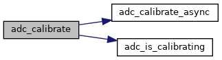
◆ adc_calibrate()
| void adc_calibrate | ( | uint32_t | adc | ) |
Start ADC calibration and wait for it to finish.
The ADC must have been powered down for at least 2 ADC clock cycles, then powered on before calibration starts
- Parameters
-
adc ADC Block register address base ADC register base addresses
Definition at line 374 of file adc.c.
References adc_calibrate_async(), and adc_is_calibrating().
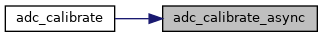
◆ adc_calibrate_async()
| void adc_calibrate_async | ( | uint32_t | adc | ) |
Start the ADC calibration and immediately return.
- See also
- adc_calibrate
- adc_is_calibrate
- Parameters
-
adc ADC Block register address base ADC register base addresses
Definition at line 353 of file adc.c.
References ADC_CR2, and ADC_CR2_CAL.
Referenced by adc_calibrate().
◆ adc_calibration()
| void adc_calibration | ( | uint32_t | adc | ) |
ADC Calibration.
- Deprecated:
- replaced by adc_calibrate/_async/_is_calibrating The calibration data for the ADC is recomputed. The hardware clears the calibration status flag when calibration is complete. This function does not return until this happens and the ADC is ready for use.
The ADC must have been powered down for at least 2 ADC clock cycles, then powered on. before calibration starts
- Parameters
-
[in] adc Unsigned int32. ADC block register address base ADC register base addresses.
Definition at line 341 of file adc.c.
References ADC_CR2, and ADC_CR2_CAL.
◆ adc_clear_flag()
| void adc_clear_flag | ( | uint32_t | adc, |
| uint32_t | flag | ||
| ) |
Clear a Status Flag.
- Parameters
-
[in] adc Unsigned int32. ADC register address base ADC register base addresses [in] flag Unsigned int32. Status register flag ADC Status Register Flags.
Definition at line 771 of file adc_common_v1.c.
References ADC_SR.
◆ adc_disable_analog_watchdog_injected()
| void adc_disable_analog_watchdog_injected | ( | uint32_t | adc | ) |
ADC Disable Analog Watchdog for Injected Conversions.
- Parameters
-
[in] adc Unsigned int32. ADC block register address base ADC register base addresses
Definition at line 161 of file adc_common_v1.c.
References ADC_CR1.
◆ adc_disable_analog_watchdog_regular()
| void adc_disable_analog_watchdog_regular | ( | uint32_t | adc | ) |
ADC Disable Analog Watchdog for Regular Conversions.
- Parameters
-
[in] adc Unsigned int32. ADC block register address base ADC register base addresses.
Definition at line 135 of file adc_common_v1.c.
References ADC_CR1.
◆ adc_disable_automatic_injected_group_conversion()
| void adc_disable_automatic_injected_group_conversion | ( | uint32_t | adc | ) |
ADC Disable Automatic Injected Conversions.
- Parameters
-
[in] adc Unsigned int32. ADC block register address base ADC register base addresses
Definition at line 251 of file adc_common_v1.c.
References ADC_CR1.
◆ adc_disable_awd_interrupt()
| void adc_disable_awd_interrupt | ( | uint32_t | adc | ) |
ADC Disable Analog Watchdog Interrupt.
- Parameters
-
[in] adc Unsigned int32. ADC block register address base ADC register base addresses
Definition at line 372 of file adc_common_v1.c.
References ADC_CR1.
◆ adc_disable_discontinuous_mode_injected()
| void adc_disable_discontinuous_mode_injected | ( | uint32_t | adc | ) |
ADC Disable Discontinuous Mode for Injected Conversions.
- Parameters
-
[in] adc Unsigned int32. ADC block register address base ADC register base addresses
Definition at line 223 of file adc_common_v1.c.
References ADC_CR1.
◆ adc_disable_discontinuous_mode_regular()
| void adc_disable_discontinuous_mode_regular | ( | uint32_t | adc | ) |
ADC Disable Discontinuous Mode for Regular Conversions.
- Parameters
-
[in] adc Unsigned int32. ADC block register address base ADC register base addresses
Definition at line 197 of file adc_common_v1.c.
References ADC_CR1.
◆ adc_disable_dma()
| void adc_disable_dma | ( | uint32_t | adc | ) |
ADC Disable DMA Transfers.
- Parameters
-
[in] adc Unsigned int32. ADC block register address base ADC register base addresses
Definition at line 746 of file adc_common_v1.c.
References ADC_CR2.
◆ adc_disable_eoc_interrupt()
| void adc_disable_eoc_interrupt | ( | uint32_t | adc | ) |
ADC Disable Regular End-Of-Conversion Interrupt.
- Parameters
-
[in] adc Unsigned int32. ADC block register address base ADC register base addresses
Definition at line 395 of file adc_common_v1.c.
References ADC_CR1.
◆ adc_disable_eoc_interrupt_injected()
| void adc_disable_eoc_interrupt_injected | ( | uint32_t | adc | ) |
ADC Disable Injected End-Of-Conversion Interrupt.
- Parameters
-
[in] adc Unsigned int32. ADC block register address base ADC register base addresses
Definition at line 350 of file adc_common_v1.c.
References ADC_CR1.
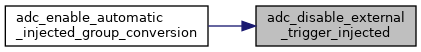
◆ adc_disable_external_trigger_injected()
| void adc_disable_external_trigger_injected | ( | uint32_t | adc | ) |
ADC Disable an External Trigger for Injected Channels.
- Parameters
-
[in] adc Unsigned int32. ADC block register address base ADC register base addresses.
Definition at line 306 of file adc.c.
References ADC_CR2.
Referenced by adc_enable_automatic_injected_group_conversion().
◆ adc_disable_external_trigger_regular()
| void adc_disable_external_trigger_regular | ( | uint32_t | adc | ) |
ADC Disable an External Trigger for Regular Channels.
- Parameters
-
[in] adc Unsigned int32. ADC block register address base ADC register base addresses.
Definition at line 252 of file adc.c.
References ADC_CR2.
◆ adc_disable_scan_mode()
| void adc_disable_scan_mode | ( | uint32_t | adc | ) |
ADC Disable Scan Mode.
- Parameters
-
[in] adc Unsigned int32. ADC block register address base ADC register base addresses
Definition at line 328 of file adc_common_v1.c.
References ADC_CR1.
◆ adc_disable_temperature_sensor()
| void adc_disable_temperature_sensor | ( | void | ) |
◆ adc_enable_analog_watchdog_injected()
| void adc_enable_analog_watchdog_injected | ( | uint32_t | adc | ) |
ADC Enable Analog Watchdog for Injected Conversions.
The analog watchdog allows the monitoring of an analog signal between two threshold levels. The thresholds must be preset. Comparison is done before data alignment takes place, so the thresholds are left-aligned.
- Parameters
-
[in] adc Unsigned int32. ADC block register address base ADC register base addresses
Definition at line 150 of file adc_common_v1.c.
References ADC_CR1, and ADC_CR1_JAWDEN.
◆ adc_enable_analog_watchdog_on_all_channels()
| void adc_enable_analog_watchdog_on_all_channels | ( | uint32_t | adc | ) |
ADC Enable Analog Watchdog for All Regular and/or Injected Channels.
The analog watchdog allows the monitoring of an analog signal between two threshold levels. The thresholds must be preset. Comparison is done before data alignment takes place, so the thresholds are left-aligned.
- Note
- The analog watchdog must be enabled for either or both of the regular or injected channels. If neither are enabled, the analog watchdog feature will be disabled. adc_enable_analog_watchdog_injected, adc_enable_analog_watchdog_regular.
- Parameters
-
[in] adc Unsigned int32. ADC block register address base ADC register base addresses
Definition at line 272 of file adc_common_v1.c.
References ADC_CR1.
◆ adc_enable_analog_watchdog_on_selected_channel()
| void adc_enable_analog_watchdog_on_selected_channel | ( | uint32_t | adc, |
| uint8_t | channel | ||
| ) |
ADC Enable Analog Watchdog for a Selected Channel.
The analog watchdog allows the monitoring of an analog signal between two threshold levels. The thresholds must be preset. Comparison is done before data alignment takes place, so the thresholds are left-aligned.
- Note
- The analog watchdog must be enabled for either or both of the regular or injected channels. If neither are enabled, the analog watchdog feature will be disabled. If both are enabled, the same channel number is monitored. adc_enable_analog_watchdog_injected, adc_enable_analog_watchdog_regular.
- Parameters
-
[in] adc Unsigned int32. ADC block register address base ADC register base addresses [in] channel Unsigned int8. ADC channel number ADC watchdog channel
Definition at line 294 of file adc_common_v1.c.
References ADC_CR1, ADC_CR1_AWDCH_MAX, and ADC_CR1_AWDSGL.
◆ adc_enable_analog_watchdog_regular()
| void adc_enable_analog_watchdog_regular | ( | uint32_t | adc | ) |
ADC Enable Analog Watchdog for Regular Conversions.
The analog watchdog allows the monitoring of an analog signal between two threshold levels. The thresholds must be preset.
- Parameters
-
[in] adc Unsigned int32. ADC block register address base ADC register base addresses.
Definition at line 123 of file adc_common_v1.c.
References ADC_CR1, and ADC_CR1_AWDEN.
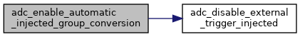
◆ adc_enable_automatic_injected_group_conversion()
| void adc_enable_automatic_injected_group_conversion | ( | uint32_t | adc | ) |
ADC Enable Automatic Injected Conversions.
The ADC converts a defined injected group of channels immediately after the regular channels have been converted. The external trigger on the injected channels is disabled as required.
- Parameters
-
[in] adc Unsigned int32. ADC block register address base ADC register base addresses
Definition at line 239 of file adc_common_v1.c.
References ADC_CR1, ADC_CR1_JAUTO, and adc_disable_external_trigger_injected().
◆ adc_enable_awd_interrupt()
| void adc_enable_awd_interrupt | ( | uint32_t | adc | ) |
ADC Enable Analog Watchdog Interrupt.
- Parameters
-
[in] adc Unsigned int32. ADC block register address base ADC register base addresses
Definition at line 361 of file adc_common_v1.c.
References ADC_CR1, and ADC_CR1_AWDIE.
◆ adc_enable_discontinuous_mode_injected()
| void adc_enable_discontinuous_mode_injected | ( | uint32_t | adc | ) |
ADC Enable Discontinuous Mode for Injected Conversions.
In this mode the ADC converts sequentially one channel of the defined group of injected channels, cycling back to the first channel in the group once the entire group has been converted.
- Parameters
-
[in] adc Unsigned int32. ADC block register address base ADC register base addresses
Definition at line 212 of file adc_common_v1.c.
References ADC_CR1, and ADC_CR1_JDISCEN.
◆ adc_enable_discontinuous_mode_regular()
| void adc_enable_discontinuous_mode_regular | ( | uint32_t | adc, |
| uint8_t | length | ||
| ) |
ADC Enable Discontinuous Mode for Regular Conversions.
In this mode the ADC converts, on each trigger, a subgroup of up to 8 of the defined regular channel group. The subgroup is defined by the number of consecutive channels to be converted. After a subgroup has been converted the next trigger will start conversion of the immediately following subgroup of the same length or until the whole group has all been converted. When the the whole group has been converted, the next trigger will restart conversion of the subgroup at the beginning of the whole group.
- Parameters
-
[in] adc Unsigned int32. ADC block register address base ADC register base addresses [in] length Unsigned int8. Number of channels in the group ADC Number of channels in discontinuous mode.
Definition at line 182 of file adc_common_v1.c.
References ADC_CR1, ADC_CR1_DISCEN, and ADC_CR1_DISCNUM_SHIFT.
◆ adc_enable_dma()
| void adc_enable_dma | ( | uint32_t | adc | ) |
ADC Enable DMA Transfers.
- Parameters
-
[in] adc Unsigned int32. ADC block register address base ADC register base addresses
Definition at line 735 of file adc_common_v1.c.
References ADC_CR2, and ADC_CR2_DMA.
◆ adc_enable_eoc_interrupt()
| void adc_enable_eoc_interrupt | ( | uint32_t | adc | ) |
ADC Enable Regular End-Of-Conversion Interrupt.
- Parameters
-
[in] adc Unsigned int32. ADC block register address base ADC register base addresses
Definition at line 384 of file adc_common_v1.c.
References ADC_CR1, and ADC_CR1_EOCIE.
◆ adc_enable_eoc_interrupt_injected()
| void adc_enable_eoc_interrupt_injected | ( | uint32_t | adc | ) |
ADC Enable Injected End-Of-Conversion Interrupt.
- Parameters
-
[in] adc Unsigned int32. ADC block register address base ADC register base addresses
Definition at line 339 of file adc_common_v1.c.
References ADC_CR1, and ADC_CR1_JEOCIE.
◆ adc_enable_external_trigger_injected()
| void adc_enable_external_trigger_injected | ( | uint32_t | adc, |
| uint32_t | trigger | ||
| ) |
ADC Enable an External Trigger for Injected Channels.
This enables an external trigger for set of defined injected channels.
For ADC1 and ADC2
- Timer 1 TRGO event
- Timer 1 CC4 event
- Timer 2 TRGO event
- Timer 2 CC1 event
- Timer 3 CC4 event
- Timer 4 TRGO event
- EXTI (TIM8 CC4 is also possible on some devices, see datasheet)
- Software Start
For ADC3
- Timer 1 TRGO event
- Timer 1 CC4 event
- Timer 4 CC3 event
- Timer 8 CC2 event
- Timer 8 CC4 event
- Timer 5 TRGO event
- Timer 5 CC4 event
- Software Start
- Parameters
-
[in] adc Unsigned int32. ADC block register address base ADC register base addresses. [in] trigger Unsigned int8. Trigger identifier ADC Injected Trigger Identifier for ADC1 for ADC1 and ADC2, or ADC Injected Trigger Identifier for ADC3 for ADC3.
Definition at line 288 of file adc.c.
References ADC_CR2, ADC_CR2_JEXTSEL_MASK, and ADC_CR2_JEXTTRIG.
◆ adc_enable_external_trigger_regular()
| void adc_enable_external_trigger_regular | ( | uint32_t | adc, |
| uint32_t | trigger | ||
| ) |
ADC Enable an External Trigger for Regular Channels.
This enables an external trigger for set of defined regular channels.
For ADC1 and ADC2
- Timer 1 CC1 event
- Timer 1 CC2 event
- Timer 1 CC3 event
- Timer 2 CC2 event
- Timer 3 TRGO event
- Timer 4 CC4 event
- EXTI (TIM8_TRGO is also possible on some devices, see datasheet)
- Software Start
For ADC3
- Timer 3 CC1 event
- Timer 2 CC3 event
- Timer 1 CC3 event
- Timer 8 CC1 event
- Timer 8 TRGO event
- Timer 5 CC1 event
- Timer 5 CC3 event
- Software Start
- Parameters
-
[in] adc Unsigned int32. ADC block register address base ADC register base addresses. [in] trigger Unsigned int8. Trigger identifier ADC Trigger Identifier for ADC1 and ADC2 for ADC1 and ADC2, or ADC Trigger Identifier for ADC3 for ADC3.
Definition at line 235 of file adc.c.
References ADC_CR2, ADC_CR2_EXTSEL_MASK, and ADC_CR2_EXTTRIG.
◆ adc_enable_scan_mode()
| void adc_enable_scan_mode | ( | uint32_t | adc | ) |
ADC Set Scan Mode.
In this mode a conversion consists of a scan of the predefined set of channels, regular and injected, each channel conversion immediately following the previous one. It can use single, continuous or discontinuous mode.
- Parameters
-
[in] adc Unsigned int32. ADC block register address base ADC register base addresses
Definition at line 317 of file adc_common_v1.c.
References ADC_CR1, and ADC_CR1_SCAN.
◆ adc_enable_temperature_sensor()
| void adc_enable_temperature_sensor | ( | void | ) |
ADC Enable The Temperature Sensor.
This enables both the sensor and the reference voltage measurements on channels 16 and 17.
Definition at line 186 of file adc.c.
References ADC1, ADC_CR2, and ADC_CR2_TSVREFE.
◆ adc_eoc()
| bool adc_eoc | ( | uint32_t | adc | ) |
ADC Read the End-of-Conversion Flag.
This flag is set after all channels of a regular or injected group have been converted.
- Parameters
-
[in] adc Unsigned int32. ADC block register address base ADC register base addresses
- Returns
- bool. End of conversion flag.
Definition at line 435 of file adc_common_v1.c.
References ADC_SR, and ADC_SR_EOC.
◆ adc_eoc_injected()
| bool adc_eoc_injected | ( | uint32_t | adc | ) |
ADC Read the End-of-Conversion Flag for Injected Conversion.
This flag is set after all channels of an injected group have been converted.
- Parameters
-
[in] adc Unsigned int32. ADC block register address base ADC register base addresses
- Returns
- bool. End of conversion flag.
Definition at line 449 of file adc_common_v1.c.
References ADC_SR, and ADC_SR_JEOC.
◆ adc_get_flag()
| bool adc_get_flag | ( | uint32_t | adc, |
| uint32_t | flag | ||
| ) |
Read a Status Flag.
- Parameters
-
[in] adc Unsigned int32. ADC register address base ADC register base addresses [in] flag Unsigned int32. Status register flag ADC Status Register Flags.
- Returns
- boolean: flag set.
Definition at line 759 of file adc_common_v1.c.
References ADC_SR.
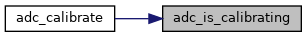
◆ adc_is_calibrating()
| bool adc_is_calibrating | ( | uint32_t | adc | ) |
Is the ADC Calibrating?
- Parameters
-
adc ADC Block register address base ADC register base addresses
- Returns
- true if the adc is currently calibrating
Definition at line 363 of file adc.c.
References ADC_CR2, and ADC_CR2_CAL.
Referenced by adc_calibrate().
◆ adc_power_off()
| void adc_power_off | ( | uint32_t | adc | ) |
ADC Off.
Turn off the ADC to reduce power consumption to a few microamps.
- Parameters
-
[in] adc Unsigned int32. ADC block register address base ADC register base addresses.
Definition at line 108 of file adc_common_v1.c.
References ADC_CR2.
◆ adc_power_on()
| void adc_power_on | ( | uint32_t | adc | ) |
ADC Power On.
If the ADC is in power-down mode then it is powered up. The application needs to wait a time of about 3 microseconds for stabilization before using the ADC. If the ADC is already on this function call has no effect. NOTE Common with F37x
- Parameters
-
[in] adc Unsigned int32. ADC block register address base ADC register base addresses
Definition at line 107 of file adc.c.
References ADC_CR2, and ADC_CR2_ADON.
◆ adc_read_injected()
| uint32_t adc_read_injected | ( | uint32_t | adc, |
| uint8_t | reg | ||
| ) |
ADC Read from an Injected Conversion Result Register.
The result read back from the selected injected result register (one of four) is 12 bits, right or left aligned within the first 16 bits. The result can have a negative value if the injected channel offset has been set
- See also
- adc_set_injected_offset.
- Parameters
-
[in] adc Unsigned int32. ADC block register address base ADC register base addresses [in] reg Unsigned int8. Register number (1 ... 4).
- Returns
- Unsigned int32 conversion result.
Definition at line 483 of file adc_common_v1.c.
◆ adc_read_regular()
| uint32_t adc_read_regular | ( | uint32_t | adc | ) |
ADC Read from the Regular Conversion Result Register.
The result read back is 12 bits, right or left aligned within the first 16 bits. For ADC1 only, the higher 16 bits will hold the result from ADC2 if an appropriate dual mode has been set
- See also
- adc_set_dual_mode.
- Parameters
-
[in] adc Unsigned int32. ADC block register address base ADC register base addresses
- Returns
- Unsigned int32 conversion result.
Definition at line 465 of file adc_common_v1.c.
References ADC_DR.
◆ adc_reset_calibration()
| void adc_reset_calibration | ( | uint32_t | adc | ) |
ADC Initialize Calibration Registers.
This resets the calibration registers. It is not clear if this is required to be done before every calibration operation.
- Parameters
-
[in] adc Unsigned int32. ADC block register address base ADC register base addresses.
Definition at line 321 of file adc.c.
References ADC_CR2, and ADC_CR2_RSTCAL.
◆ adc_set_continuous_conversion_mode()
| void adc_set_continuous_conversion_mode | ( | uint32_t | adc | ) |
ADC Enable Continuous Conversion Mode.
In this mode the ADC starts a new conversion of a single channel or a channel group immediately following completion of the previous channel group conversion.
- Parameters
-
[in] adc Unsigned int32. ADC block register address base ADC register base addresses
Definition at line 507 of file adc_common_v1.c.
References ADC_CR2, and ADC_CR2_CONT.
◆ adc_set_dual_mode()
| void adc_set_dual_mode | ( | uint32_t | mode | ) |
ADC Set Dual A/D Mode.
The dual mode uses ADC1 as master and ADC2 in a slave arrangement. This setting is applied to ADC1 only. Start of conversion when triggered can cause simultaneous conversion with ADC2, or alternate conversion. Regular and injected conversions can be configured, each one being separately simultaneous or alternate.
Fast interleaved mode starts ADC1 immediately on trigger, and ADC2 seven clock cycles later.
Slow interleaved mode starts ADC1 immediately on trigger, and ADC2 fourteen clock cycles later, followed by ADC1 fourteen cycles later again. This can only be used on a single channel.
Alternate trigger mode must occur on an injected channel group, and alternates between the ADCs on each trigger.
Note that sampling must not overlap between ADCs on the same channel.
Dual A/D converter modes possible:
- IND: Independent mode.
- CRSISM: Combined regular simultaneous + injected simultaneous mode.
- CRSATM: Combined regular simultaneous + alternate trigger mode.
- CISFIM: Combined injected simultaneous + fast interleaved mode.
- CISSIM: Combined injected simultaneous + slow interleaved mode.
- ISM: Injected simultaneous mode only.
- RSM: Regular simultaneous mode only.
- FIM: Fast interleaved mode only.
- SIM: Slow interleaved mode only.
- ATM: Alternate trigger mode only.
- Parameters
-
[in] mode Unsigned int32. Dual mode selection from ADC Mode Selection
Definition at line 171 of file adc.c.
References ADC1_CR1.
◆ adc_set_injected_offset()
| void adc_set_injected_offset | ( | uint32_t | adc, |
| uint8_t | reg, | ||
| uint32_t | offset | ||
| ) |
ADC Set the Injected Channel Data Offset.
This value is subtracted from the injected channel results after conversion is complete, and can result in negative results. A separate value can be specified for each injected data register.
- Parameters
-
[in] adc Unsigned int32. ADC block register address base ADC register base addresses [in] reg Unsigned int8. Register number (1 ... 4). [in] offset Unsigned int32.
Definition at line 662 of file adc_common_v1.c.
◆ adc_set_injected_sequence()
| void adc_set_injected_sequence | ( | uint32_t | adc, |
| uint8_t | length, | ||
| uint8_t | channel[] | ||
| ) |
ADC Set an Injected Channel Conversion Sequence.
Defines a sequence of channels to be converted as an injected group with a length from 1 to 4 channels. If this is called during conversion, the current conversion is reset and conversion begins again with the newly defined group.
- Parameters
-
[in] adc Unsigned int32. ADC block register address base ADC register base addresses [in] length Unsigned int8. Number of channels in the group. [in] channel Unsigned int8[]. Set of channels in sequence, integers 0..18
Definition at line 630 of file adc_common_v1.c.
References ADC_JSQR, ADC_JSQR_JL_VAL, and ADC_JSQR_JSQ_VAL.
◆ adc_set_left_aligned()
| void adc_set_left_aligned | ( | uint32_t | adc | ) |
ADC Set the Data as Left Aligned.
- Parameters
-
[in] adc Unsigned int32. ADC block register address base ADC register base addresses.
Definition at line 408 of file adc_common_v1.c.
References ADC_CR2, and ADC_CR2_ALIGN.
◆ adc_set_regular_sequence()
| void adc_set_regular_sequence | ( | uint32_t | adc, |
| uint8_t | length, | ||
| uint8_t | channel[] | ||
| ) |
ADC Set a Regular Channel Conversion Sequence.
Define a sequence of channels to be converted as a regular group with a length from 1 to ADC_REGULAR_SEQUENCE_MAX channels. If this is called during conversion, the current conversion is reset and conversion begins again with the newly defined group.
- Parameters
-
[in] adc Unsigned int32. ADC block base address ADC register base addresses. [in] length Unsigned int8. Number of channels in the group. [in] channel Unsigned int8[]. Set of channels in sequence, integers 0..31.
Definition at line 574 of file adc_common_v1.c.
References ADC_SQR1, ADC_SQR1_L_LSB, ADC_SQR2, ADC_SQR3, and ADC_SQR_MAX_CHANNELS_REGULAR.
◆ adc_set_right_aligned()
| void adc_set_right_aligned | ( | uint32_t | adc | ) |
ADC Set the Data as Right Aligned.
- Parameters
-
[in] adc Unsigned int32. ADC block register address base ADC register base addresses.
Definition at line 420 of file adc_common_v1.c.
References ADC_CR2.
◆ adc_set_sample_time()
| void adc_set_sample_time | ( | uint32_t | adc, |
| uint8_t | channel, | ||
| uint8_t | time | ||
| ) |
ADC Set the Sample Time for a Single Channel.
The sampling time can be selected in ADC clock cycles from 1.5 to 239.5.
- Parameters
-
[in] adc Unsigned int32. ADC block register address base ADC register base addresses. [in] channel Unsigned int8. ADC Channel integer 0..18 or from ADC Channel Numbers. [in] time Unsigned int8. Sampling time selection from ADC Sample Time Selection for All Channels. - NOTE Common with f2 and f37x and f4
◆ adc_set_sample_time_on_all_channels()
| void adc_set_sample_time_on_all_channels | ( | uint32_t | adc, |
| uint8_t | time | ||
| ) |
ADC Set the Sample Time for All Channels.
The sampling time can be selected in ADC clock cycles from 1.5 to 239.5, same for all channels.
- Parameters
-
[in] adc Unsigned int32. ADC block register address base ADC register base addresses. [in] time Unsigned int8. Sampling time selection from ADC Sample Time Selection for All Channels. - NOTE Common with f2 and f37x and f4
◆ adc_set_single_conversion_mode()
| void adc_set_single_conversion_mode | ( | uint32_t | adc | ) |
ADC Enable Single Conversion Mode.
In this mode the ADC performs a conversion of one channel or a channel group and stops.
- Parameters
-
[in] adc Unsigned int32. ADC block register address base ADC register base addresses.
Definition at line 523 of file adc_common_v1.c.
References ADC_CR2.
◆ adc_set_watchdog_high_threshold()
| void adc_set_watchdog_high_threshold | ( | uint32_t | adc, |
| uint16_t | threshold | ||
| ) |
ADC Set Analog Watchdog Upper Threshold.
- Parameters
-
[in] adc Unsigned int32. ADC block register address base ADC register base addresses [in] threshold Upper threshold value, 12bit right aligned.
Definition at line 535 of file adc_common_v1.c.
References ADC_HT_MSK, and ADC_HTR.
◆ adc_set_watchdog_low_threshold()
| void adc_set_watchdog_low_threshold | ( | uint32_t | adc, |
| uint16_t | threshold | ||
| ) |
ADC Set Analog Watchdog Lower Threshold.
- Parameters
-
[in] adc Unsigned int32. ADC block register address base ADC register base addresses [in] threshold Lower threshold value, 12bit right aligned.
Definition at line 551 of file adc_common_v1.c.
References ADC_LT_MSK, and ADC_LTR.
◆ adc_start_conversion_direct()
| void adc_start_conversion_direct | ( | uint32_t | adc | ) |
ADC Start a Conversion Without Trigger.
This initiates a conversion by software without a trigger. The ADC needs to be powered on before this is called, otherwise this function has no effect.
Note that this is not available in other STM32F families. To ensure code compatibility, enable triggering and use a software trigger source
- See also
- adc_start_conversion_regular.
- Parameters
-
[in] adc Unsigned int32. ADC block register address base ADC register base addresses
Definition at line 127 of file adc.c.
References ADC_CR2, and ADC_CR2_ADON.
◆ adc_start_conversion_injected()
| void adc_start_conversion_injected | ( | uint32_t | adc | ) |
ADC Software Triggered Conversion on Injected Channels.
This starts conversion on a set of defined injected channels if the ADC trigger is set to be a software trigger. It is cleared by hardware once conversion starts.
Special F1 Note this is a software trigger and requires triggering to be enabled and the trigger source to be set appropriately otherwise conversion will not start. This is not the same as the ADC start conversion operation.
- Parameters
-
[in] adc Unsigned int32. ADC block register address base ADC register base addresses.
Definition at line 719 of file adc_common_v1.c.
References ADC_CR2, and ADC_CR2_JSWSTART.
◆ adc_start_conversion_regular()
| void adc_start_conversion_regular | ( | uint32_t | adc | ) |
ADC Software Triggered Conversion on Regular Channels.
This starts conversion on a set of defined regular channels if the ADC trigger is set to be a software trigger. It is cleared by hardware once conversion starts.
Special F1 Note this is a software trigger and requires triggering to be enabled and the trigger source to be set appropriately otherwise conversion will not start. This is not the same as the ADC start conversion operation.
- Parameters
-
[in] adc Unsigned int32. ADC block register address base ADC register base addresses.
Definition at line 695 of file adc_common_v1.c.
References ADC_CR2, and ADC_CR2_SWSTART.